In this post T.K. Hareendran will try to gain some insight into the electronics of a cheap PWM Power MOSFET Module. The module under the spotlight is the pretty common FR120N MOSFET Control Module which is a simple N-channel logic-level compatible power MOSFET board with an optically isolated control input.

FR120N Module
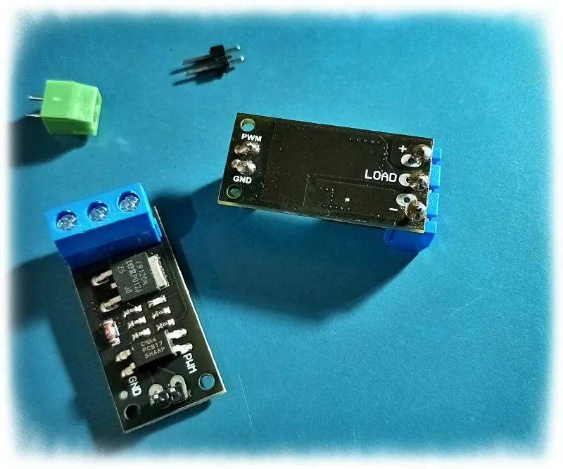
The FR120N module comes as a package with the following parts:
- FR120N MOSFET Control Module
- 3-pin Screw Terminal
- 2-pin Screw Terminal
- 2-pin male header strip
Here are the advertised key features (you have to take everything listed here with a grain of salt
- One channel switching output
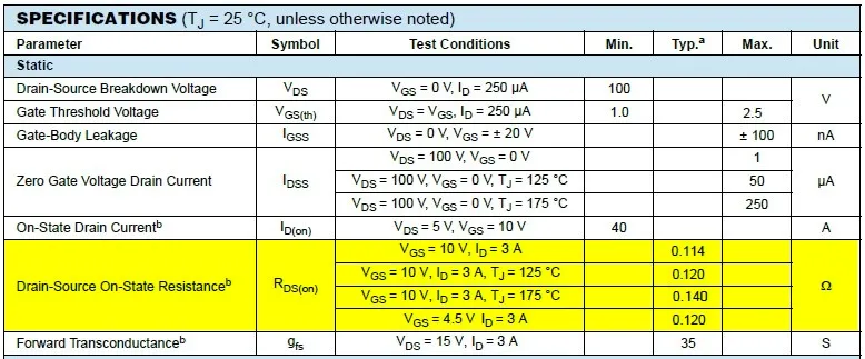
- Ultra-low 0.114Ω RDS(on) resistance
- 2.5V to 20V input control voltage with opto-isolation
- 6V to 28V output switching voltage
- 15A continuous current handling capability
- 3.3V and 5V logic compatible
- 0 to 20kHz PWM frequency
Note, however, that the module does not have a flyback diode onboard. Therefore, when using the module for inductive loads, an external flyback diode should be employed to avoid possible damage due to inductive kickbacks.
Module Shematic
Now see its schematic drawn by me:
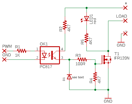
A detailed analysis is not necessary here as this is a simple and straightforward circuit configuration. However, there are some significant points to note. Let us get to it.
PC817 photocoupler
→ The main purpose of the PC817 photocoupler in this module (https://datasheet.lcsc.com/lcsc/1809251512_Wuxi-China-Resources-Huajing-Microelectronics-PC817C_C115500.pdf) is to completely isolate the low-power input circuit from the high-power output circuitry.
In practice, the value of the current limiting resistor R1 sets the forward current (IF) for the infrared light sender located inside the optocoupler.
Assuming a 5V TTL control input voltage, the forward current through the infrared light sender is close to 4mA (5V-1.2V/1KΩ = 3.8mA, where 1.2V is the typical forward voltage drop VF across the infrared light sender at 4mA).
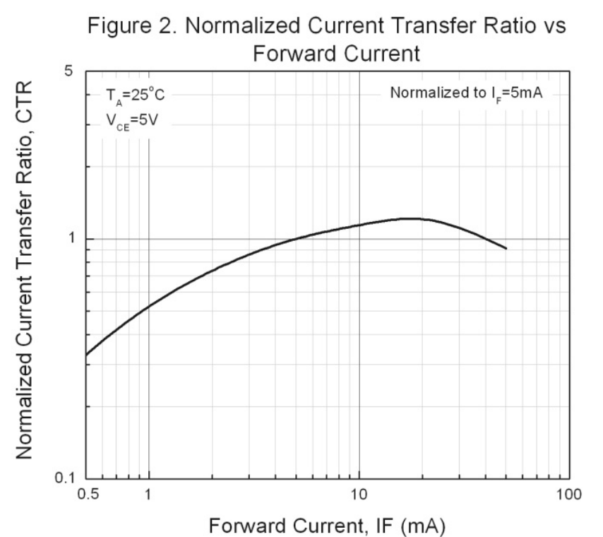
The graph below shows that ideally the CTR for the PC817 will be about 115% with a forward current of 4mA, which denotes that the optocoupler’s output current in this case will be around 4mA x 115% = 4.6mA (VCE = 5V).
FR120N mosfet
→ The FR120N is a 15A/100V N-channel power mosfet.
According to the datasheet, it is a ‘pwm optimized’ power mosfet (https://datasheet.lcsc.com/szlcsc/2010051735_VBsemi-Elec-FR120N_C879050.pdf).
Note that the FR120N mosfet has the claimed 0.114Ω RDS (on) only when VGS is 10V and ID is 3A (TJ = 25°C).
So to meet this condition, the output switching voltage (LOAD +) should be at least 20VDC, because the two 4.7KΩ resistors (R2-R4) form a potential divider approximately halving the gate voltage.
Also, the FR120N mosfet has an RDS(on) rated at 4.5V but half of the advertised minimum output switching voltage of 6V is not enough to ensure the mosfet is fully conducting with a reasonably low effective resistance – the minimum output switching voltage must be 9V to get it.
Likewise, 28V output switching will destroy the mosfet because a voltage close to 14V will reach its gate, but the maximum VGS of the mosfet is +/-20V only. However, this can be prevented by using a 10V zener diode as D1 to keep the VGS within specification. In my module D1 is just a 1N4148 diode, but in some other modules a fast recovery diode RGL1D is seen, neither of which makes much sense (at least to me).
PWM drive
→ According to the datasheet, FR120N is a pwm optimized mosfet which has
been designed to give the highest efficiency available for a given on-resistance in switching applications such as dc-to-dc conversion.
In principle, reducing gate charge is one way in which pwm optimized mosfets cut power losses (another component of power loss is crossover losses). These types of mosfets usually provide a very low gate charge per unit of on-resistance, in addition to fast switching times. The result is reduced gate drive and crossover losses.
One should keep in mind at this point that the output drive capability of a standard photocoupler is typically not adequate to turn most mosfets on and off in no time.
For example, this particular very low RDS(on) mosfet has a moderately high dynamic gate charge and input capacitance. So, to get faster switching times, a dedicated gate driver chip or circuitry is required for very high frequency pwm applications (that is not what this cheap module is for, though).
As a side note, for those looking to make their own pwm mosfet modules, here are some recommended mosfets:
- FDS4410 (Single N-channel)
- FDS6898AZ (Dual N-channel)
- IRLR7843 (Single N-channel)
Furthermore, rembmer when it comes to pwm, the speed of the photocoupler is a key factor. Ensure the minimum pulse width of the pwm signal must be longer than the switching speed of the photocoupler (https://www.analogictips.com/selecting-optocoupler-isolate-pwm/). Also keep in mind that photocouplers vary widely in many respects, including in how devices are characterized from manufacturer to manufacturer.
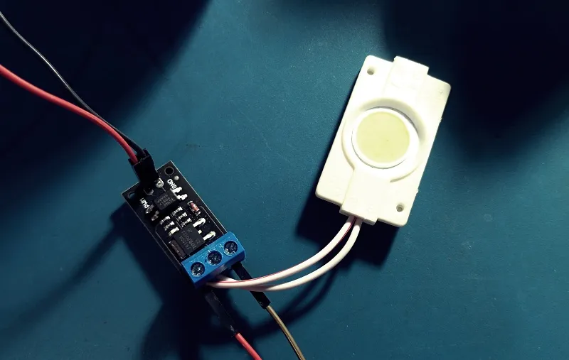
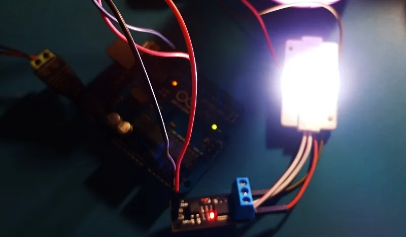
Basic Test
For a quick test, I chose a 12V Coin LED as the output load and used an Arduino PWM signal as the drive pulse.
Here is the Arduino Sketch:
int lampDrive = 9; //drive signal output

int fadeValue = 5;


void setup() {
  pinMode(lampDrive, OUTPUT);
}

void loop()  {
/*
lamp brightness increases slowly
and
then stay high in the end */

  if (fadeValue < 255)
  {

    if (fadeValue >= 245)

    {

      fadeValue = 255;

    }

    else

    {
      fadeValue++;
    }

    analogWrite(lampDrive, fadeValue);
    delay(100);

  }

}
Final Thoughts
This FR120N module is good for basic on/off operation like driving a heater, or pwm control like dimming a set of lights.
An important point to note is that this module demands a 5V TTL control signal input and a minimum 12V output/load switching voltage to provide a reasonable performance. Your perspective may differ from mine, but this module will be fine for 500Hz-1kHz Arduino PWM.
In closing, I just have to say this is a neat mosfet module to have on hand when building a project that requires an isolated power switch. This is one of the cheap Chinese mosfet modules that have appeared on the market in recent years. It is very reasonably priced. But as with most things in life, you get what you pay for,
This article was written on December 23, 2023 by T.K. Hareendran 12.29.2025,the original can be read here.