RelatedDifferences and Applications of Transistors, MOSFETs, and IGBTs So, for electronic switching, should MOSFETs, transistors, or IGBTs be used?
Bipolar transistors
For high power transistor switches, it is common to use a triple Darlington configuration. The figure below shows the circuit diagram of a typical “Fuji” three-stage Darlington transistor used in the inverter stage of an AC Motor Speed Controller.
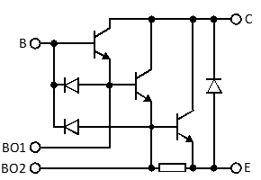
Figure 1: Triple Darlington bipolar transistor
To get these devices to switch on to a low saturation voltage, (3V typical) a high base current is needed. To get them to turn off quickly so as to minimise switching losses, a high negative “suck-out” base current is needed. Because of this, they are comparatively inefficient and were superceded by IGBTs over 30 years ago.
IGBTs
The insulated gate bipolar transistor (IGBT) effectively replaced the triple Darlington in power switching applications. This is a voltage controlled device, where switching is achieved by driving a gate terminal with a voltage. The main current handling stage is a bipolar transistor. The symbol for an IGBT is shown in Figure 2(a). The IGBT is modelled as MOSFET transistor driving a PNP transistor, as shown in Figure 2(b). The IGBT is turned on by taking the gate to a positive voltage (+15 V). It is turned off quickly by taking the gate to a negative voltage (-5 V).
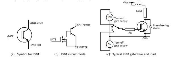
Figure 2: IGBT symbol, circuit model, gate drive
Advantages of IGBT over triple Darlington:
- Simplified and lower power gate drive circuit
- Faster switching speeds (2 – 4 times) and lower switching losses allowing higher modulation frequency
- Lower on-state saturation voltage (2V typical) allowing for smaller heatsinks
The IGBT continues to be used for inverters and VFDs with output voltages between say 100Vac and 690Vac. However at lower output voltages the (fixed) saturation voltage becomes significant and converter efficiency reduces
Power MOSFETs
The power metal oxide semiconductor field effect transistor (MOSFET) is designed to be a fast-acting power switch. The MOSFET is a voltage controlled device which needs negligible power to drive it. They are available as N-channel and P-channel, however N-channel is preferred because of a lower on-state resistance.
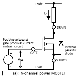
Figure 3: N-channel MOSFET
Switching times of a MOSFET are very fast when compared with those of the IGBT – typically five times faster. Turn-on and turn-off losses are very low, thus enabling operation in excess of 100 kHz.
As the rated breakdown voltage of a MOSFET increases, the on-state resistance RDS(on) increases significantly. Thus high voltage devices can have high conduction losses when used as switches.
MOSFETs may be chosen over IGBTs in these applications:
- Where a high switching frequency (e.g. inaudible to humans) is required
- For inverter or chopper circuits operating below (say) 100Vdc, where the MOSFET on-state dissipation is less than that of an equivalently rated IGBT.
Author: Ian McKenzie First published here
power electronics, transformer design, motor control, PLC programming
George Voltman, Project Manager at Electrical Engineering (2015-present) · Author has 1.4K answers and 7.8M answer viewsDec 19