This article was first published here
By combining a basic RC Low Pass Filter circuit with an operational amplifier we can create an Active Low Pass Filter circuit complete with amplification
Active filters such as an active low pass filter, are filter circuits that use an operational amplifier (op-amp) as the their main amplifying device along with some resistors and capacitors to provide a filter like performance at low frequencies.
Basic first-order passive filter circuits, such as a low pass or a high pass filter can be constructed using just a single resistor in series with a non-polarized capacitor connected across a sinusoidal input signal. The main disadvantage of passive filters is that the amplitude of the output signal is less than that of the input signal, ie, the gain is never greater than unity and that the load impedance affects the filters characteristics.
With passive filter circuits containing multiple stages, this loss in signal amplitude called “Attenuation” can become quiet severe. One way of restoring or controlling this loss of signal is by using amplification through the use of Active Filters.
As their name implies, Active Filters contain active components such as operational amplifiers, transistors or FET’s within their circuit design. They draw their power from an external power source and use it to boost or amplify the output signal.
Filter amplification can also be used to either shape or alter the frequency response of the filter circuit by producing a more selective output response, making the output bandwidth of the filter more narrower or even wider. Then the main difference between a “passive filter” and an “active filter” is amplification.
An active filter generally uses an operational amplifier (op-amp) within its design and in the Operational Amplifier tutorial we saw that an Op-amp has a high input impedance, a low output impedance and a voltage gain determined by the resistor network within its feedback loop.
Unlike a passive high pass filter which has in theory an infinite high frequency response, the maximum frequency response of an active filter is limited to the Gain/Bandwidth product (or open loop gain) of the operational amplifier being used. Still, active filters are generally much easier to design than passive filters, they produce good performance characteristics, very good accuracy with a steep roll-off and low noise when used with a good circuit design.
Active Low Pass Filter
The most common and easily understood active filter is the Active Low Pass Filter. Its principle of operation and frequency response is exactly the same as those for the previously seen passive filter, the only difference this time is that it uses an op-amp for amplification and gain control. The simplest form of a low pass active filter is to connect an inverting or non-inverting amplifier, the same as those discussed in the Op-amp tutorial, to the basic RC low pass filter circuit as shown.
First Order Low Pass Filter
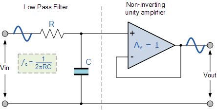
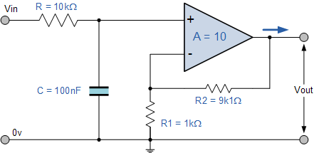
This first-order low pass active filter, consists simply of a passive RC filter stage providing a low frequency path to the input of a non-inverting operational amplifier. The amplifier is configured as a voltage-follower (Buffer) giving it a DC gain of one, Av = +1 or unity gain as opposed to the previous passive RC filter which has a DC gain of less than unity.
The advantage of this configuration is that the op-amps high input impedance prevents excessive loading on the filters output while its low output impedance prevents the filters cut-off frequency point from being affected by changes in the impedance of the load.
While this configuration provides good stability to the filter, its main disadvantage is that it has no voltage gain above one. However, although the voltage gain is unity the power gain is very high as its output impedance is much lower than its input impedance. If a voltage gain greater than one is required we can use the following filter circuit.
Active Low Pass Filter with Amplification
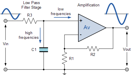
The frequency response of the circuit will be the same as that for the passive RC filter, except that the amplitude of the output is increased by the pass band gain, AF of the amplifier. For a non-inverting amplifier circuit, the magnitude of the voltage gain for the filter is given as a function of the feedback resistor ( R2 ) divided by its corresponding input resistor ( R1 ) value and is given as:

Therefore, the gain of an active low pass filter as a function of frequency will be:
Gain of a first-order low pass filter
- Where:
- AF = the pass band gain of the filter, (1 + R2/R1)
- ƒ = the frequency of the input signal in Hertz, (Hz)
- ƒc = the cut-off frequency in Hertz, (Hz)
Thus, the operation of a low pass active filter can be verified from the frequency gain equation above as:
- 1. At very low frequencies, ƒ < ƒc

- 2. At the cut-off frequency, ƒ = ƒc

- 3. At very high frequencies, ƒ > ƒc

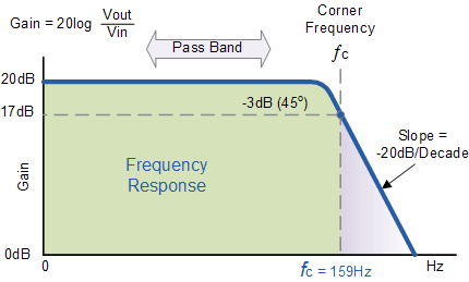
Thus, the Active Low Pass Filter has a constant gain AF from 0Hz to the high frequency cut-off point, ƒC. At ƒC the gain is 0.707AF, and after ƒC it decreases at a constant rate as the frequency increases. That is, when the frequency is increased tenfold (one decade), the voltage gain is divided by 10.
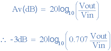
In other words, the gain decreases 20dB (= 20*log(10)) each time the frequency is increased by 10. When dealing with filter circuits the magnitude of the pass band gain of the circuit is generally expressed in decibels or dB as a function of the voltage gain, and this is defined as:
Magnitude of Voltage Gain in (dB)
Active Low Pass Filter Example No1
Design a non-inverting active low pass filter circuit that has a gain of ten at low frequencies, a high frequency cut-off or corner frequency of 159Hz and an input impedance of 10KΩ.
The voltage gain of a non-inverting operational amplifier is given as:

Assume a value for resistor R1 of 1kΩ rearranging the formula above gives a value for R2 of:

So for a voltage gain of 10, R1 = 1kΩ and R2 = 9kΩ. However, a 9kΩ resistor does not exist so the next preferred value of 9k1Ω is used instead. Converting this voltage gain to an equivalent decibel dB value gives:

The cut-off or corner frequency (ƒc) is given as being 159Hz with an input impedance of 10kΩ. This cut-off frequency can be found by using the formula:
 | where ƒc = 159Hz and R = 10kΩ. |
By rearranging the above standard formula we can find the value of the filter capacitor C as:

Thus the final low pass filter circuit along with its frequency response is given below as:
Low Pass Filter Circuit
Frequency Response Curve

If the external impedance connected to the input of the filter circuit changes, this impedance change would also affect the corner frequency of the filter (components connected together in series or parallel). One way of avoiding any external influence is to place the capacitor in parallel with the feedback resistor R2 effectively removing it from the input but still maintaining the filters characteristics.
However, the value of the capacitor will change slightly from being 100nF to 110nF to take account of the 9k1Ω resistor, but the formula used to calculate the cut-off corner frequency is the same as that used for the RC passive low pass filter.

Examples of different first-order active low pass filter circuit configurations are given as:
Simplified Inverting Amplifier Filter Circuit

Here the capacitor has been moved from the op-amps input to its feedback circuit in parallel with R2. This parallel combination of C and R2 sets the -3dB point as before, but allows the amplifiers gain to roll-off indefinitely beyond the corner frequency.
At low frequencies the capacitors reactance is much higher than R2, so the dc gain is set by the standard inverting formula of: -R2/R1 = 10, for this example. As the frequency increases the capacitors reactance decreases reducing the impedance of the parallel combination of Xc||R2, until eventually at a high enough frequency, Xc reduces to zero.
The advantage here is that the circuits input impedance is now just R1 and the output signal is inverted. With the corner frequency determining components in the feedback circuit, the RC set-point is unaffected by variations in source impedance and the dc gain can be adjusted independently of the corner frequency.
Unity Gain Non-inverting Amplifier Filter Circuit
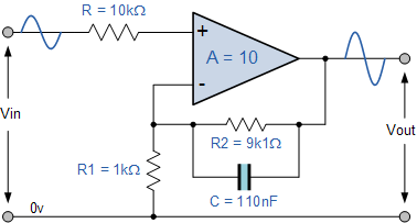
Here due to the position of the capacitor in parallel with the feedback resistor R2, the low pass corner frequency is set as before but at high frequencies the reactance of the capacitor dominates shorting out R2 reducing the amplifiers gain. At a high enough frequency the gain bottoms out at unity (0dB) as the amplifier effectively becomes a voltage follower so the gain equation becomes 1 + 0/R1 which equals 1 (unity).
Applications of Active Low Pass Filters are in audio amplifiers, equalizers or speaker systems to direct the lower frequency bass signals to the larger bass speakers or to reduce any high frequency noise or “hiss” type distortion. When used like this in audio applications the active low pass filter is sometimes called a “Bass Boost” filter.
Second-order Low Pass Active Filter
As with the passive filter, a first-order low-pass active filter can be converted into a second-order low pass filter simply by using an additional RC network in the input path. The frequency response of the second-order low pass filter is identical to that of the first-order type except that the stop band roll-off will be twice the first-order filters at 40dB/decade (12dB/octave). Therefore, the design steps required of the second-order active low pass filter are the same.
Second-order Active Low Pass Filter Circuit
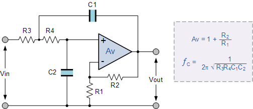
When cascading together filter circuits to form higher-order filters, the overall gain of the filter is equal to the product of each stage. For example, the gain of one stage may be 10 and the gain of the second stage may be 32 and the gain of a third stage may be 100. Then the overall gain will be 32,000, (10 x 32 x 100) as shown below.
Cascading Voltage Gain


Second-order (two-pole) active filters are important because higher-order filters can be designed using them. By cascading together first and second-order filters, filters with an order value, either odd or even up to any value can be constructed. In the next tutorial about filters, we will see that Active High Pass Filters, can be constructed by reversing the positions of the resistor and capacitor in the circuit.
Previous
Passive Band Pass Filter
Read more Tutorials inFilters
- 1. Capacitive Reactance
- 2. Passive Low Pass Filter
- 3. Passive High Pass Filter
- 4. Passive Band Pass Filter
- 5. Active Low Pass Filter
- 6. Active High Pass Filter
- 7. Active Band Pass Filter
- 8. Butterworth Filter Design
- 9. Second Order Filters
- 10. State Variable Filter
- 11. Band Stop Filter
- 12. Sallen and Key Filter
- 13. Decibels
121 Comments
Join the conversation
Notify me of follow-up comments by email.
- bathrayyan rVery nice information for designing.Posted on April 26th 2024 | 11:16 am Reply
- Aasia ChannaIt’s very informativePosted on November 22nd 2023 | 8:32 pm Reply
- Ameet Manubhai PatelVery very useful….. Thanks Everyone.
Sincerely Yours
AMP.Posted on April 21st 2023 | 6:02 am Reply - Glen MooreAs the order is increased does the filter become ‘sharper’?Posted on March 22nd 2023 | 12:47 amReply
- Ameet PatelPlease saend me more links to Opamp Circuits.Posted on April 21st 2023 | 6:04 am Reply
- Wayne StorrPlease read our tutorial about Butterworth FiltersPosted on March 22nd 2023 | 8:38 am Reply
- xyzI see too many mistakes in your schematics.
For example, C1 is at the wrong place for the Second-order Active Low Pass Filter Circuit, and you are missing a resistor to ground in at least 2 schematics.Posted on March 15th 2023 | 6:11 pmReply- Wayne StorrGuess you do not know much about active filters and how op-amps workPosted on March 15th 2023 | 8:13 pm Reply
- Mukrim MohamedThanks,helped me a lot 🙏Posted on January 17th 2023 | 12:02 am Reply
- Shanir ahmad bhatWhy not be suggest for a good thingPosted on December 11th 2022 | 8:06 pm Reply
- ابراهيم زيدان الشريفاريد بعض الاجوبه على أسألة على تصميم المرشحات الفعالهPosted on July 11th 2022 | 12:55 pm Reply
- Athman ChaiAm constructing an Audio amplified stethoscope system. Low pass filter is needed in achieving the project. Please need help on how the circuit will be i e the size of resistors and capacitors needed.
Thank youPosted on June 22nd 2022 | 12:31 pmReply- le_calculatorI mean the math is there an you should visit the passive low pass filter.
You can create a function in your preferred calculator / coding language to test for different values. Also you can calculate the cutoff frequency its explaned in the low pass passive filter page.Posted on January 06th 2023 | 10:22 pm Reply
- le_calculatorI mean the math is there an you should visit the passive low pass filter.
- KeithI cannot agree with the cut off frequency being 3dB down on the non inverting amplifier using the same calculation for fc as previously described. [1/(2xpPIxCxR2)]
I have simulated, and tested for real the situation using a 5k6 and 10nF capacitor and although theory states fc =2.842kHz (ie when Vout is 3dB down from Vin), in both the simulation and the real world tests fc is actually 3.801kHz ie 1kHz higher than calculated.
The same response is obtained using an 8n2 capacitor and 5k6b resistor. Theory says 3.466kHz
simulation and real world show 4.56kHz again approx 1kHz higher.
So either your statement is wrong or I am making a fundamental error something needs further explanation. Any ideas/Posted on September 17th 2021 | 3:55 pmReply- Wayne StorrUsing your values: Non-inverting configuration, R = 5k6 ohms, C = 10nF, at DC Xc = infinite.DC Voltage Gain, Av = 1 + (R2 / R1) = 6.6 = 16.4 dBdB gain at fc = 16.4 dB – 3 dB = 13.4 dB, therefore Av = 4.67we can confirm this: 6.6 x 0.7071 = 4.67 (the same).at fc (-3dB), R2 is in parallel with Xc (R2||Xc), thus Xc = R2(1 + (2pi*C*R2)) = 5k6/(1 + (2pi*10nF*5k6)) = 5600Ωtherefore for the capacitor frequency: f = 1 / (2pi*Xc*C) = 1 / (2pi*5600*10nF) = 2841 Hz.From tutorial fc = 1 / (2pi*C*R2) = 1/(2pi*10nF*5k6) = 2841 Hz (the same frequency).Thus, using your RC values the tutorial is correct as given.Posted on September 18th 2021 | 8:15 am Reply
- CharlesHello there,
My name is Charles. I live in Malta. I am constructing a 25W amplifier with a low pass filter. I am 69 years of age. My sideline was repairing, and or customizing guitar amps. Some three years ago I went to Brussels to buy NOS valves (tubes). Here in Malta we have a company which winds custom made transformers . Actually they supply Marshall with their transformers.Posted on September 16th 2021 | 7:43 pm Reply - Yi ZhangThe circuit under “Low Pass Filter Circuit”, my simulation (TINA) suggested that corner frequency is 159Hz as stated.However, the circuit under “Unity Gain Non-inverting Amplifier Filter Circuit”, it stated that “the low pass corner frequency is set as before”, calculate 1/(2*pi*R*C), where R = 9100 Ohm, C = 110nF indeed gives the same 159Hz, but simulation indicates that the gain at this freq is now 17.5dB instead of 17dB. The true 3dB cut off freq is now at 180Hz. Can someone explain?Posted on September 10th 2021 | 6:15 pmReply
- Jeramy HughesI don’t like this circuit. For the author to call this a “non-inverting amplifier filter” or “active low-pass filter” is quite misleading and has been a constant source of comments for years now. In any low-pass filter, you want to pass the low frequency and attenuate the high frequency (i.e. not pass the high frequency). This circuit amplifies the low frequency, but still passes the high frequency with unity gain. As a credit to they author, he has adjusted the wording at least a few times to try to clarify there remains unity gain for high frequency, however, really the author should get rid of that example altogether or explain “here is a circuit and reasons why you shouldn’t ever build it.”Posted on September 10th 2021 | 8:44 pm Reply
- Musa MansallayI like the way you present the topicsPosted on August 31st 2021 | 11:06 pm Reply
- Antok gvTolong bantu saya bikin low pass filter 5khz. Dengan skema yg pertama, berapa nilai r dan c nya?Posted on July 20th 2021 | 11:43 am Reply
- Brandon KelleyHow do I calculate the cutoff frequency of two (cascaded) low-pass filters? I’ve tried using transfer functions, but can’t seem to come up with an accurate mathematical construct that I can plug RC values into to achieve the cutoff frequency.For clairty: Im talking about two, second-order low-pass, active filters cascaded such that the first second-order filter’s output is wired into the input of the second, second-order active filter.
I get that the freq changes because we’re making the slope sharper, but is there a way to calculate this without empirical testing to make predictions? The values aren’t the same as a one second-order active filter which is simply 1/2piRC.Posted on July 04th 2021 | 8:32 amReply- Wayne StorrCascading filters together is a common method to produce higher-order filters. However, there are things you must consider when doing so.1. The corner frequency is always calculated as: Fc = 1/(2pi * sqr-root(R1.R2.R3.R4(etc.) * C1.C2.C3.C4(etc.))).
If ALL R values are equal and ALL C values are equal, then Fc = 1/(2piRC) only.2. Each RC stage creates a load or source impedance for the next or previous stage, so isolation of each stage from its neighbour is required.3. Alternatively design a 4th-order Sallen & Key, or Butterworth Filter around a single (or two) op-amps.Posted on July 05th 2021 | 9:33 amReply- Brandon KelleyLet’s say I had a voltage divider at the output of the op amp (center tapped with the inverting input of the op amp), and one resistor was a different value than the other resistors (about half, the resistor connected directly with the op amp output.1/2pi(sqrt(R1R2…C1C2…)) doesn’t appear to work for the output frequency…Based on the equations the only resistors and capacitors that should matter are R1 and C1 (R1 directly to source, C1 tapping to op amp output directly after R1)With a lone second-order active low pass filter with R1 = 1000 and C1 = .022 pF, Fc = 7234 Hz.When I cascade it with a duplicate of the above filter, the cutoff (3dB down) ends up being 5797 Hz, so the frequency at 3 dB down definitely changed, even though it seems like it shouldn’t? Is it because of the resistor at the output being a different value? If so, 1/2piSqrt(R1R2..C1C2…)) doesn’t work either if I use ALL the values or only a single value for R1 and C1.Posted on July 05th 2021 | 10:36 amReply
- Wayne Storr“With a lone second-order active low pass filter with R1 = 1000 and C1 = .022 pF, Fc = 7234 Hz.” = 7.234 GHzPosted on July 05th 2021 | 2:18 pm Reply
- Brandon KelleyLet’s say I had a voltage divider at the output of the op amp (center tapped with the inverting input of the op amp), and one resistor was a different value than the other resistors (about half, the resistor connected directly with the op amp output.1/2pi(sqrt(R1R2…C1C2…)) doesn’t appear to work for the output frequency…Based on the equations the only resistors and capacitors that should matter are R1 and C1 (R1 directly to source, C1 tapping to op amp output directly after R1)With a lone second-order active low pass filter with R1 = 1000 and C1 = .022 pF, Fc = 7234 Hz.When I cascade it with a duplicate of the above filter, the cutoff (3dB down) ends up being 5797 Hz, so the frequency at 3 dB down definitely changed, even though it seems like it shouldn’t? Is it because of the resistor at the output being a different value? If so, 1/2piSqrt(R1R2..C1C2…)) doesn’t work either if I use ALL the values or only a single value for R1 and C1.Posted on July 05th 2021 | 10:36 amReply
- JacobJust superimpose them. E.g. if you cascade two identical active filter circuits the corner frequency does not change, just the slope (which doubles).You should be able to verify this in simulation. https://wiki.analog.com/university/courses/alm1k/circuits1/alm-cir-cascade-rcPosted on July 04th 2021 | 11:53 am Reply
- Wayne StorrCascading filters together is a common method to produce higher-order filters. However, there are things you must consider when doing so.1. The corner frequency is always calculated as: Fc = 1/(2pi * sqr-root(R1.R2.R3.R4(etc.) * C1.C2.C3.C4(etc.))).
- Robert WilkinsCan a low pass filter have a high frequency cut-off to eliminate a high frequency (2700Hz) speaker feedback whine?Posted on June 06th 2021 | 3:24 amReply
- JacobLow-pass filters, by definition, block high-frequency components. You can adjust the “corner frequency” by varying the values of the components used. The further above the corner frequency a signal is, the more it is attenuated. However, if you are trying to block a specific frequency range you may want to consider another topology such “band-stop” / “notch” filters, see https://www.ti.com/lit/an/slyt235/slyt235.pdfPosted on June 07th 2021 | 3:03 pm Reply
- Wayne StorrAn electonic filter can have any cut-off frequency point determined by the designerPosted on June 06th 2021 | 7:29 am Reply
- Tapas PolangisHelpfulPosted on May 13th 2021 | 11:12 pm Reply
- Niaz Mahmud SafalThanks for this amazing tutorial.Posted on April 19th 2021 | 7:34 pm Reply
- NandeshGood, but some deep contact is needed.🙏Posted on November 23rd 2020 | 10:21 am Reply
- Juanponce fernandezVery nice tutorials. And informative for beginner more power..thank you..Posted on November 19th 2020 | 3:15 pm